[Troubleshooting][xDSL] Why can’t my xDSL routers establish an internet connection?
When you cannot successfully establish a DSL connection after setting the WAN related settings, please refer to the following steps for trouble shooting.
Before the trouble shooting steps, please confirm with your ISP regarding the xDSL type required for your xDSL service plan and confirm whether the relevant xDSL WAN setting parameters are correct and whether the cable is normal, then please check the xDSL data rate support specifications for ASUS xDSL modem router on ASUS official website
If the xDSL type provided by ISP does not match the xDSL specification of your current xDSL modem router, it means that the model does not support the services provided by the ISP and the connection cannot be successfully established. It is recommended that you purchase a model that conforms to the ISP service plan.
Please refer to the following steps to confirm the specifications of xDSL modem router on ASUS official website.
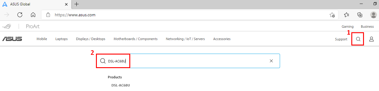
(1) Please go to ASUS Global site https://www.asus.com/ , click search
(2) Enter the model name of your ASUS xDSL modem router then press Enter Key to search. Here we take DSL-AC68U as an example.
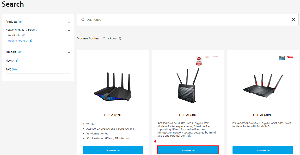
(3) Click [more] to DSL-AC68U product page.
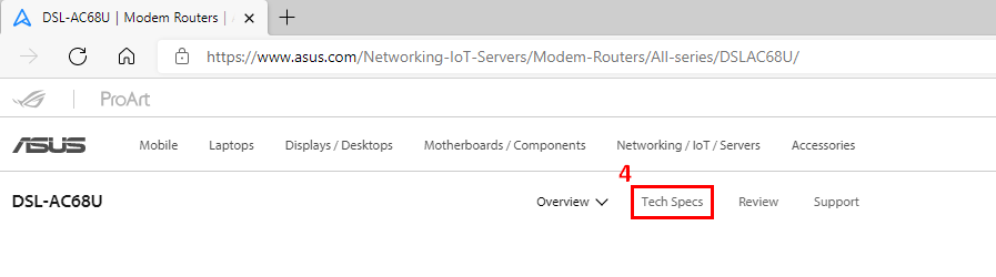
(4) Go to Tech Specs to see detail specification of DSL-AC68U
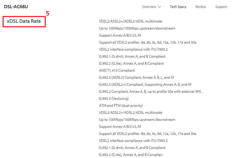
(5) The specifications for the supported xDSL type and data rate.
Trouble shooting steps
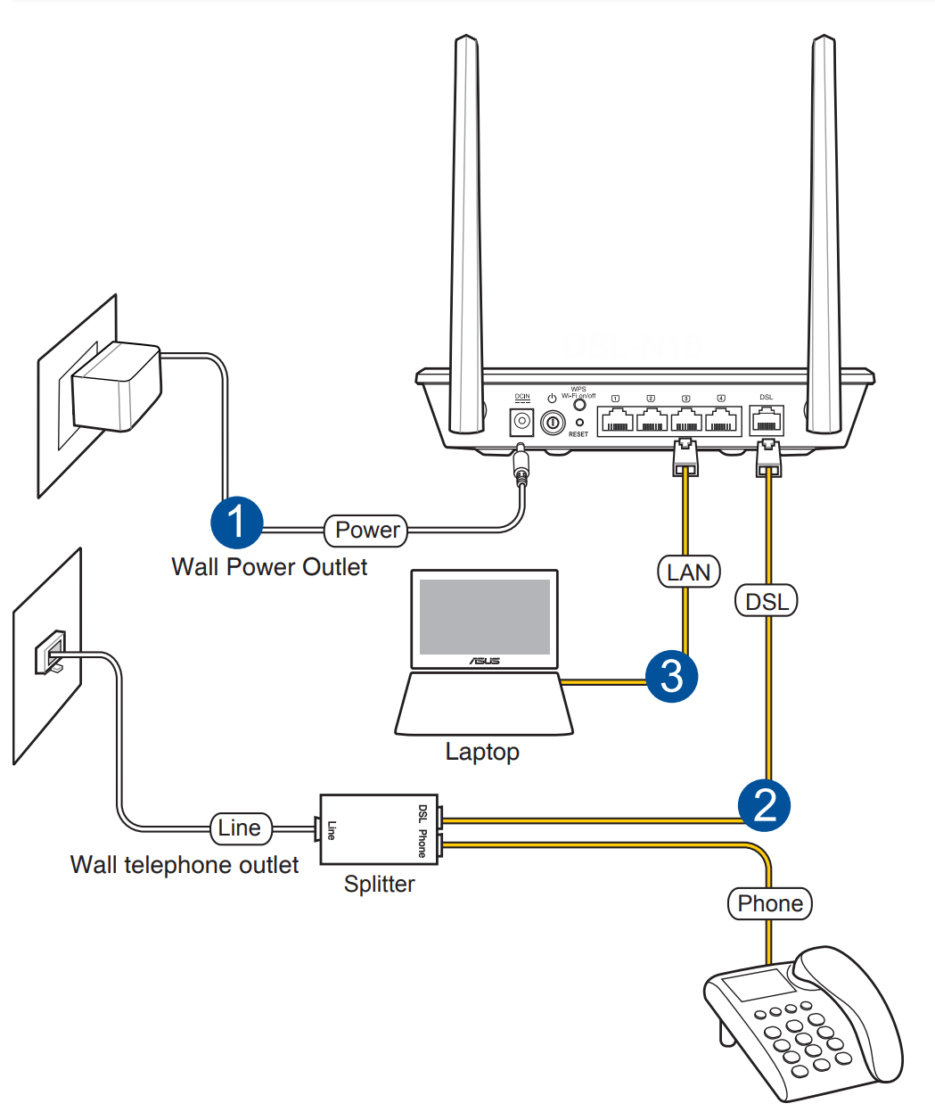
Step1. Please make sure that your DSL modem router is connected correctly.
Kindly refer to the following picture and steps to check if the power and phone cords on the DSL router are correctly plugged into the power outlet, router, phone jack and the computer.
If one of the cables is not connected, please reconnect the cables.
Detail steps about how to connect the cables correctly.
1. Insert DSL modem router’s power adapter to the DC-IN port and plug it to a power outlet.
Note 1: After connecting to power supply, remember to press the Power button to turn on the modem router.
Note 2: After turning on your DSL modem router, wait for about two to three minutes for it to boot up.
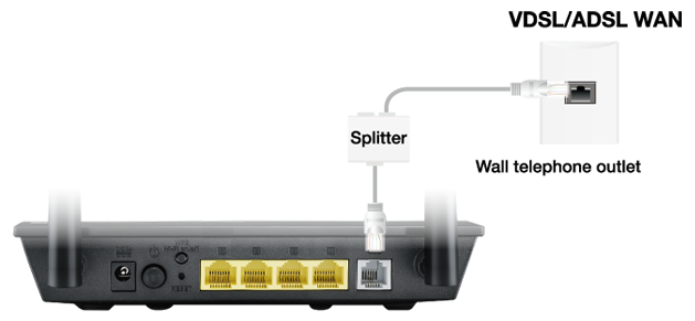
2. There are two phone cables involved here: one from the modem to the splitter and one from the splitter to the phone port on the wall. It can be either one of them.
Please take out the splitter and connect the modem to the wall line directly or replace the above two phone cables.
Connect one end of the RJ-11 cable to the DSL port of DSL modem router, and connect the other end to the DSL port of your splitter.
3. Use a network cable (RJ45) to connect your computer to DSL modem router’s LAN port.
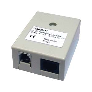
- Note that the specifications of the splitter are not the same. To avoid wrong wiring, please check the port and guidance on the splitter to confirm that the wiring is correct.
- The line may be affected by telephone signals if without the splitter. If you do not have splitter at hand, we suggest you check with your ISP if it is available.
(The picture below is an example of Splitter)
Step2. Update the firmware and have a reset for your xDSL modem router.
You can either perform a live update or update manually through router setting page(Web GUI). Before you login to Web GUI, please have your computer cable connected to your xDSL modem router, then launch the web GUI, go to Advanced settings > Administration > Firmware Upgrade tab. Click Check to verify if the latest firmware is available.
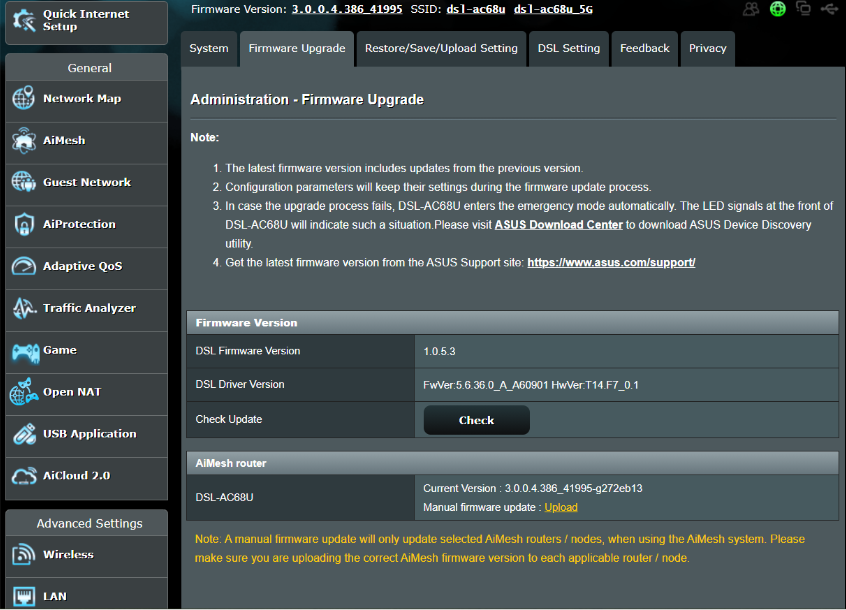
[Note] For the detail process of how to upgrade firmware, please refer to How to update the firmware of your router to the latest version ? (WebGUI)
After firmware upgrade, please restore xDSL modem router to default settings
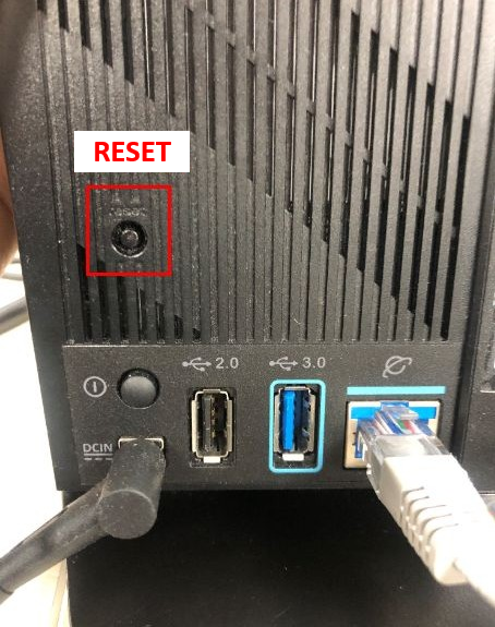
(1) Press the RESET button around 5~10 seconds until the Power LED indicator of router starts flashing, then you could stop pressing.
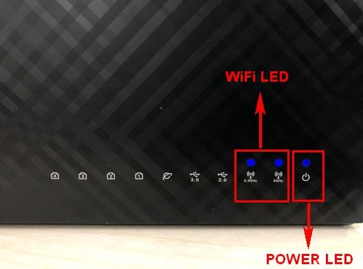
In the meantime, all the LED indicators of the router should be off. It is a normal phenomenon because the router is rebooting itself.
Wait until the Power LED indicator and Wi-Fi LED indicators are on again, you could try to enter the GUI of the router again.
Step3. After resetting the router and please make sure that the DSL LED indicator status stays on, then you may proceed with the internet setup process.
If the DSL LED does not light up, please contact ISP to make sure the line is working normally or you may try changing the RJ11 cable.
When the DSL LED lights up, please wire connect your computer to xDSL modem router then proceed the Quick Internet Setup (QIS). If still cannot establish DSL connection, please try to do it manually.
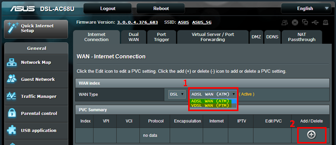
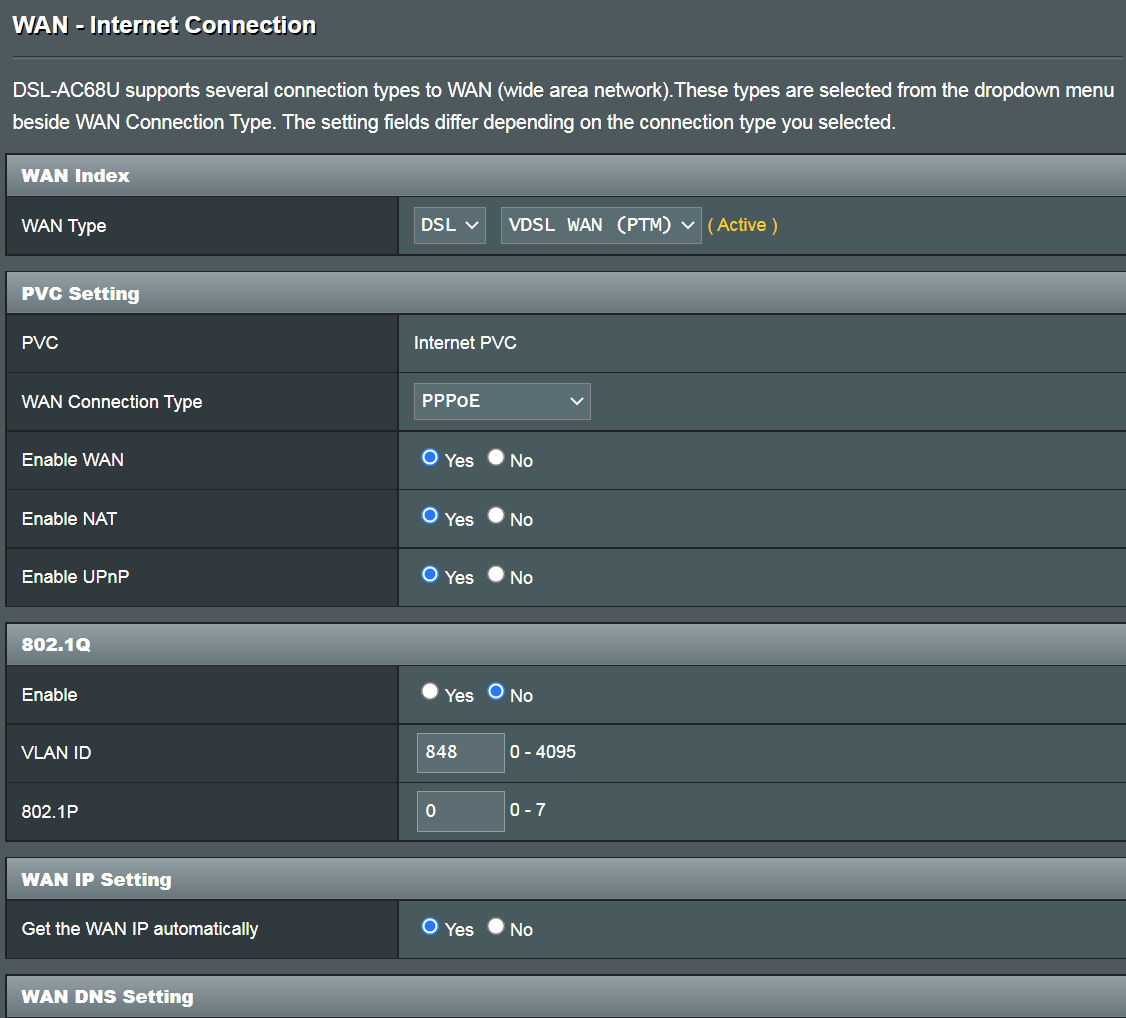
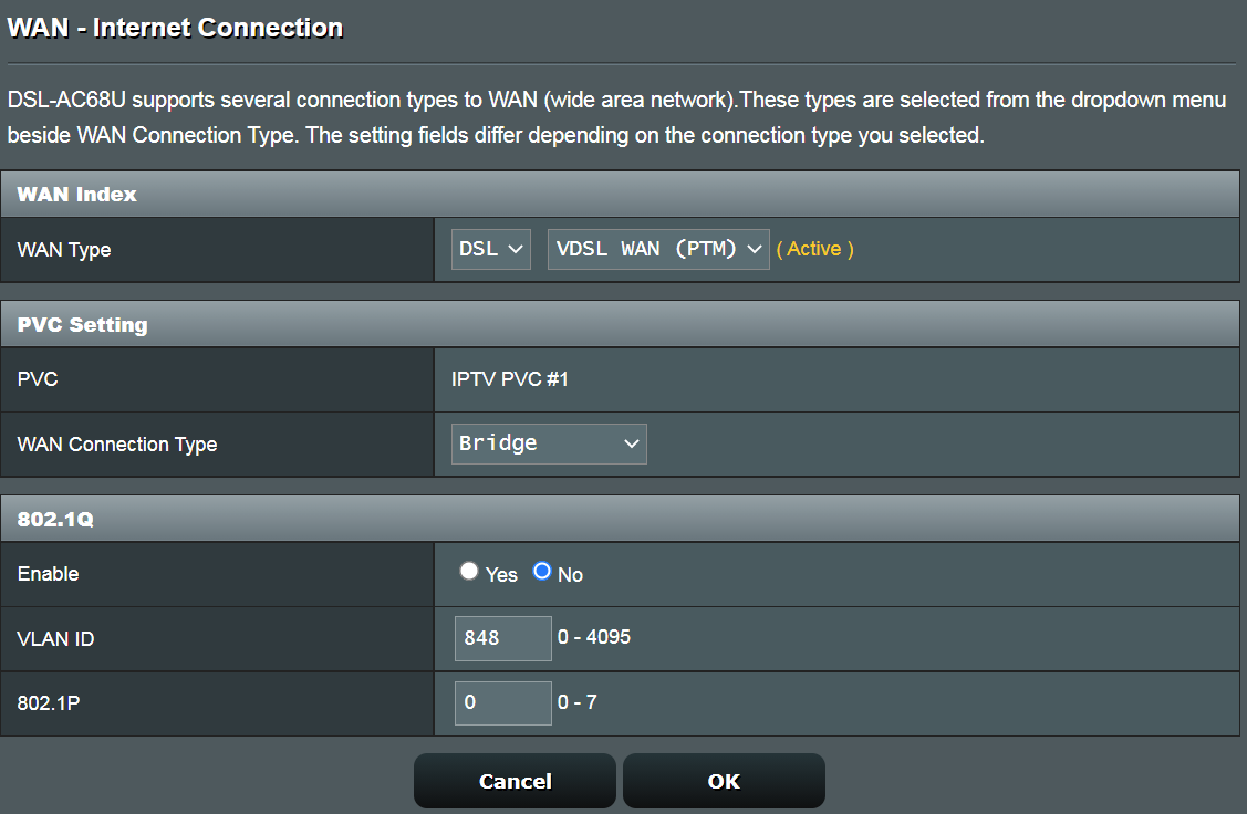
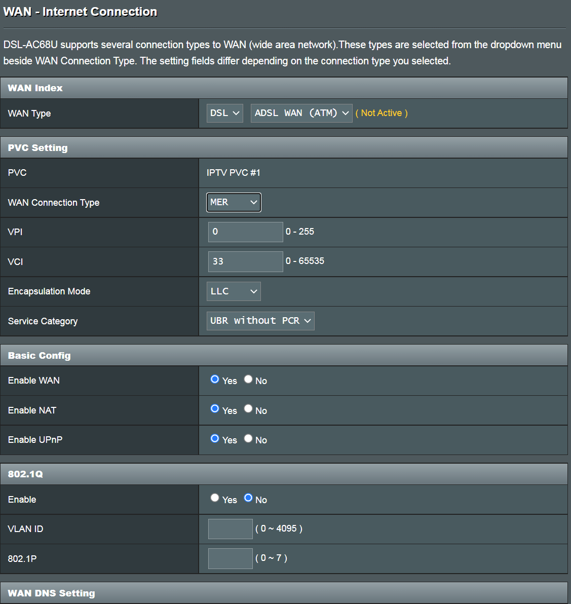
(1). On the firmware Network map page, click WAN on left side. For ADSL connection, select ATM as the Transfer Mode; for VDSL connection, please select VDSL WAN (PTM) instead. Click add to proceed.
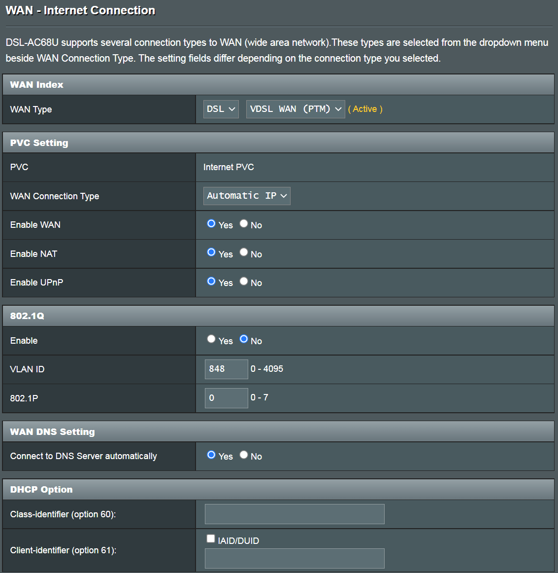
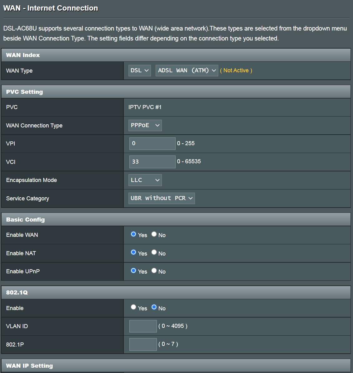
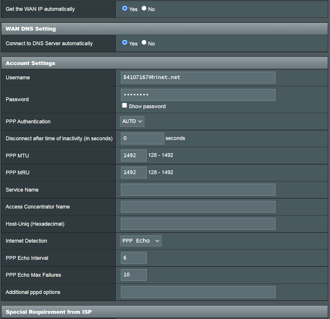
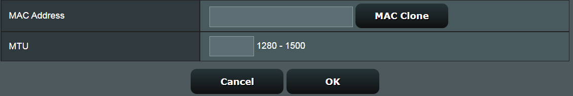
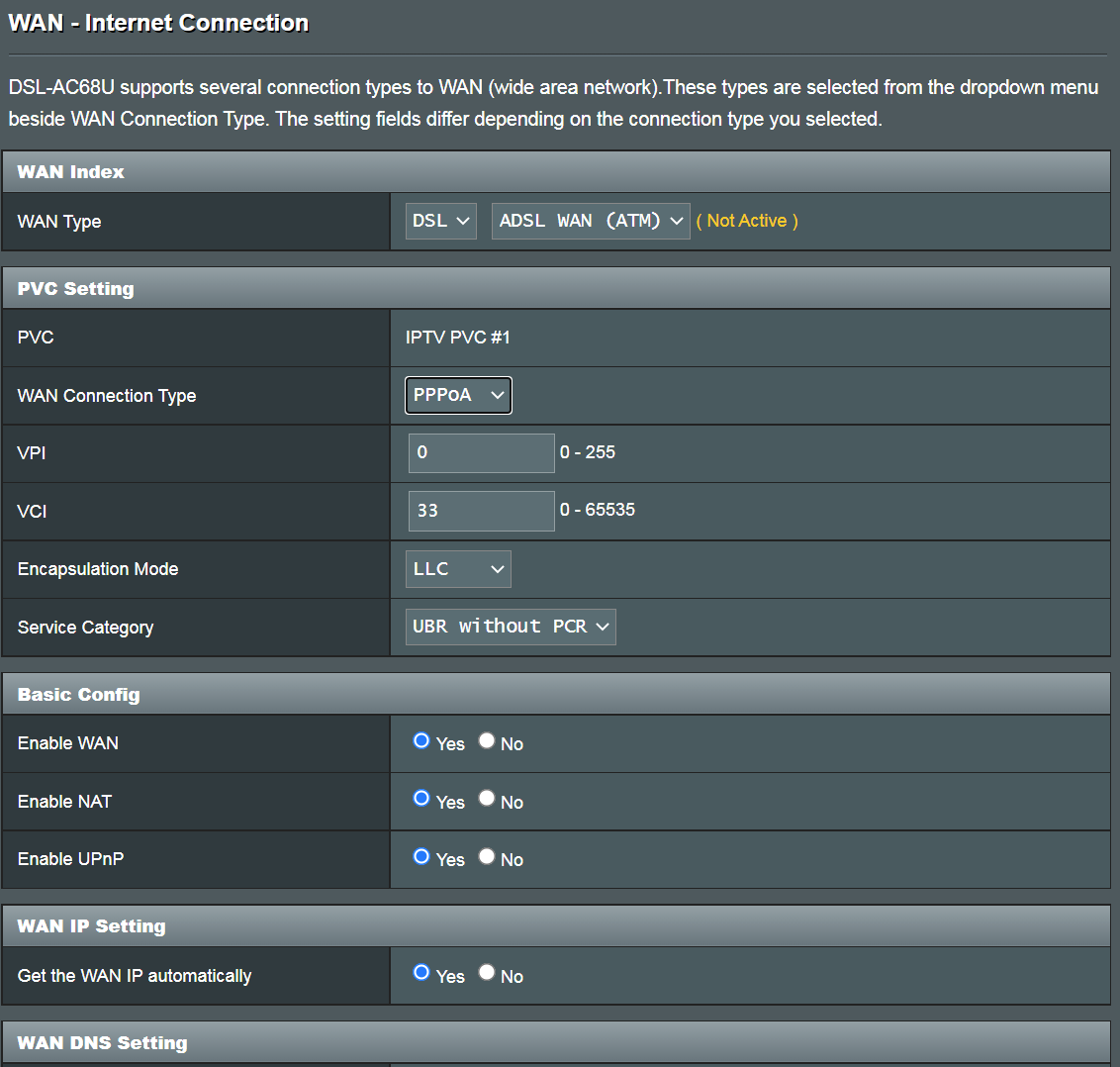
(2). Configure the VPI/VCI, Encapsulation mode, Connection type, User Name, Password and other required information, then click Save on the bottom of the page.
Note: The information entered below is just an example; these settings may vary depending on your ISP. Consult with your ISP if the router is unable to obtain a valid IP address or if you are unsure about the WAN connection type.
Transfer Mode
1. VDSL/VDSL2 WAN (PTM)
WAN Connection Type
Notice: the related information needs to confirm with your Internet Service Provider (ISP)
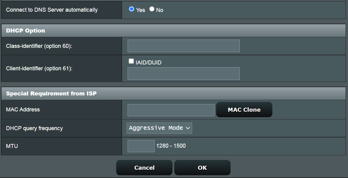
(1). Automatic IP
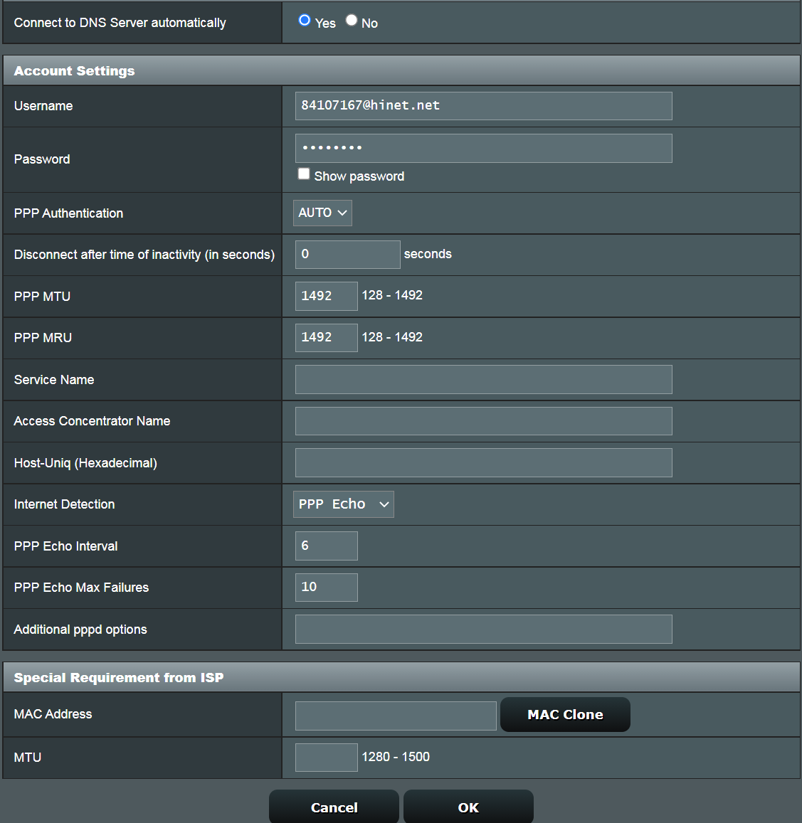
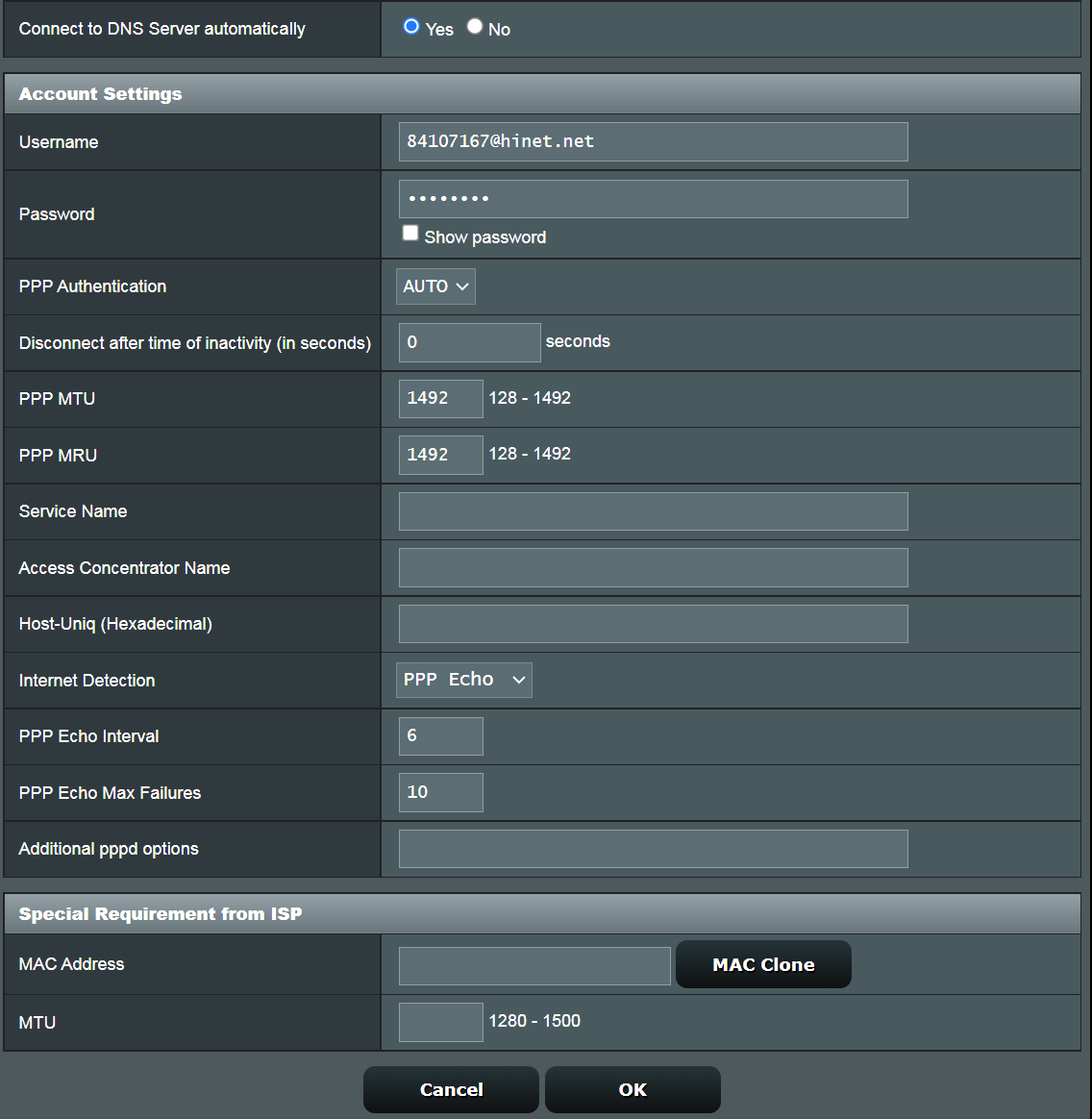
(2). PPPoE
For example:
User Name: 87875692@hinet.net
Password: xxxxxxx
(3). Static IP
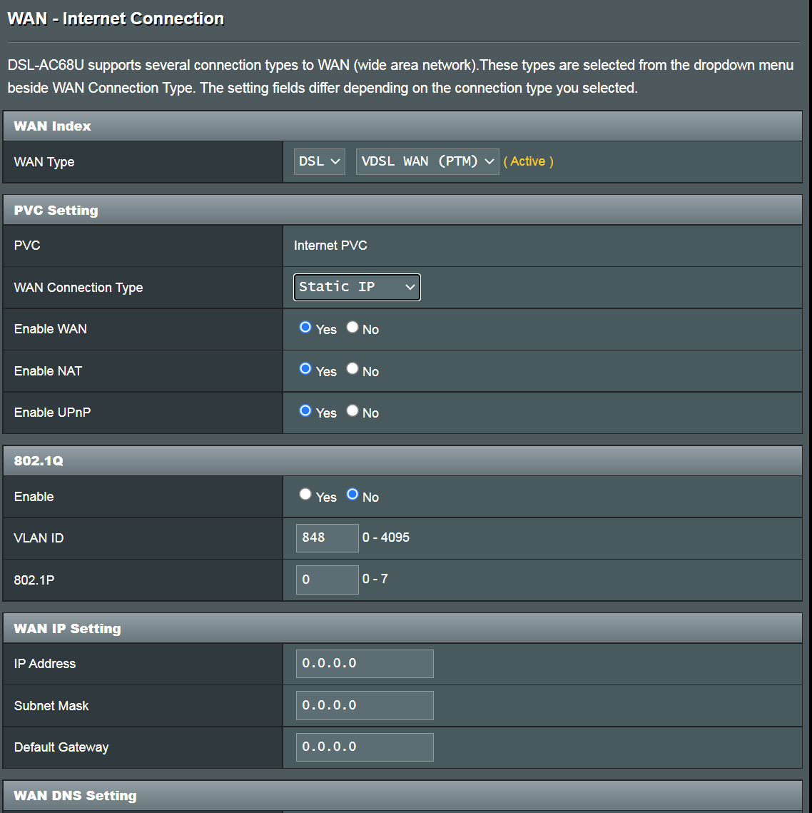
For example:
WAN IP Address: 192.168.100.33
WAN Subnet Mask: 255.255.255.0
WAN Default Gateway: 192.168.100.1
DNS Server1: 192.168.100.1
DNS Server2: 8.8.8.8
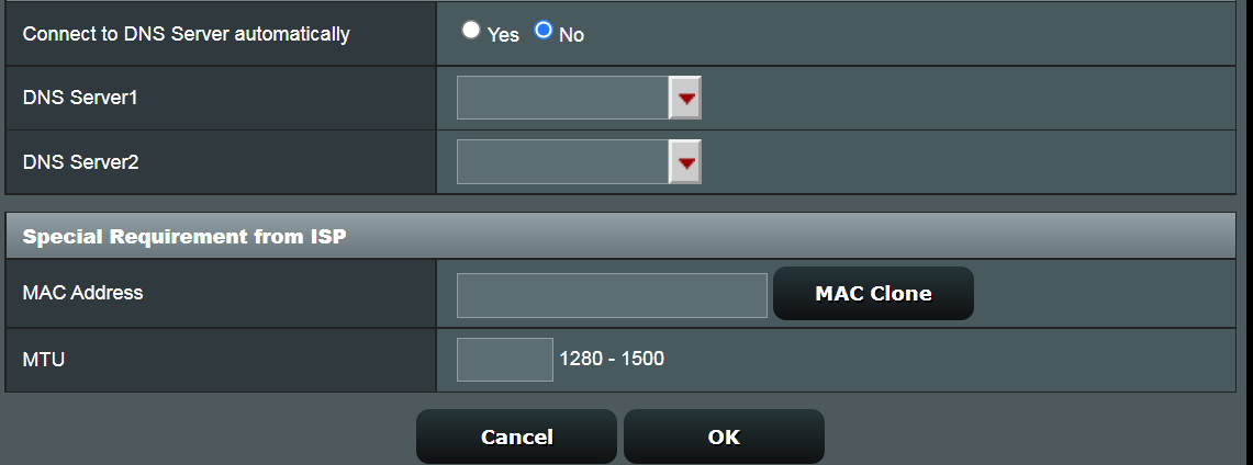
(4). Bridge
For example: (Varies from every region)
Region: Taiwan
WAN connection type: PPPoE
User Name : 87875692@hinet.net
Password: xxxxxxx
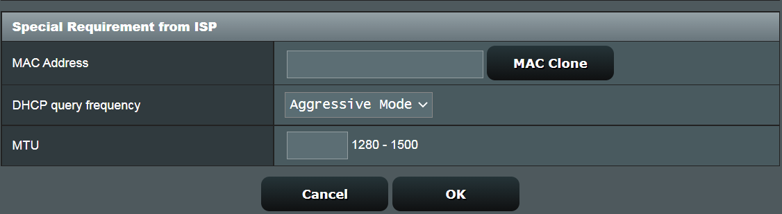
If a disconnection occurs after a period using Internet, it is recommended that you try to PPPoE > Internet detection disable (the default is PPP Echo). And then click Apply to save.
Transfer Mode
2. ADSL/ADSL2/ASDSL2+ WAN (ATM)
WAN Connection Type
Notice: the related information needs to confirm with your Internet Service Provider (ISP)
(1). Automatic IP (MER)
VPI / VCI: 0 / 33
(2). PPPoE
For example:
VPI / VCI: 0 / 33
User Name: 87875692@hinet.net
Password: xxxxxxx
(3). PPPoA
For example:
VPI / VCI: 0 / 33
User Name : 87875692@hinet.net
Password: xxxxxxx
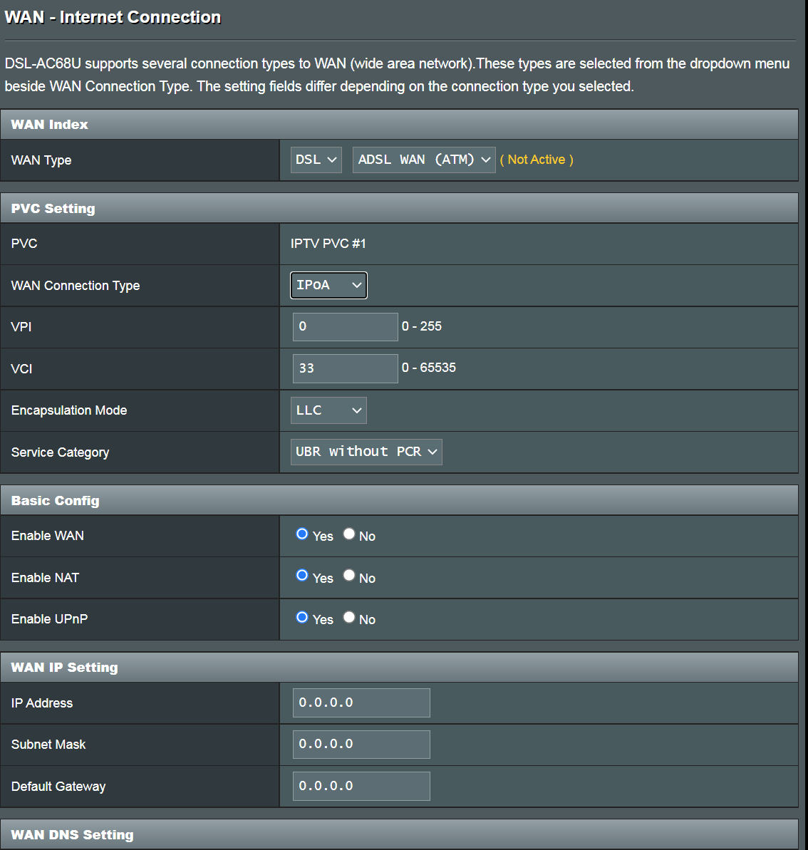
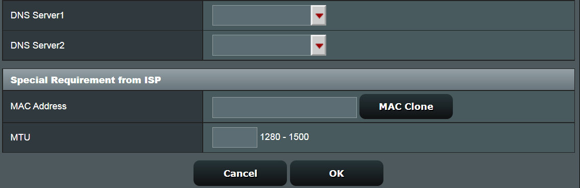
(4). IPoA
For example:
VPI / VCI: 0 / 33
WAN IP Address: 192.168.100.33
WAN Subnet Mask: 255.255.255.0
WAN Default Gateway: 192.168.100.1
DNS Server1: 192.168.100.1
DNS Server2: 8.8.8.8
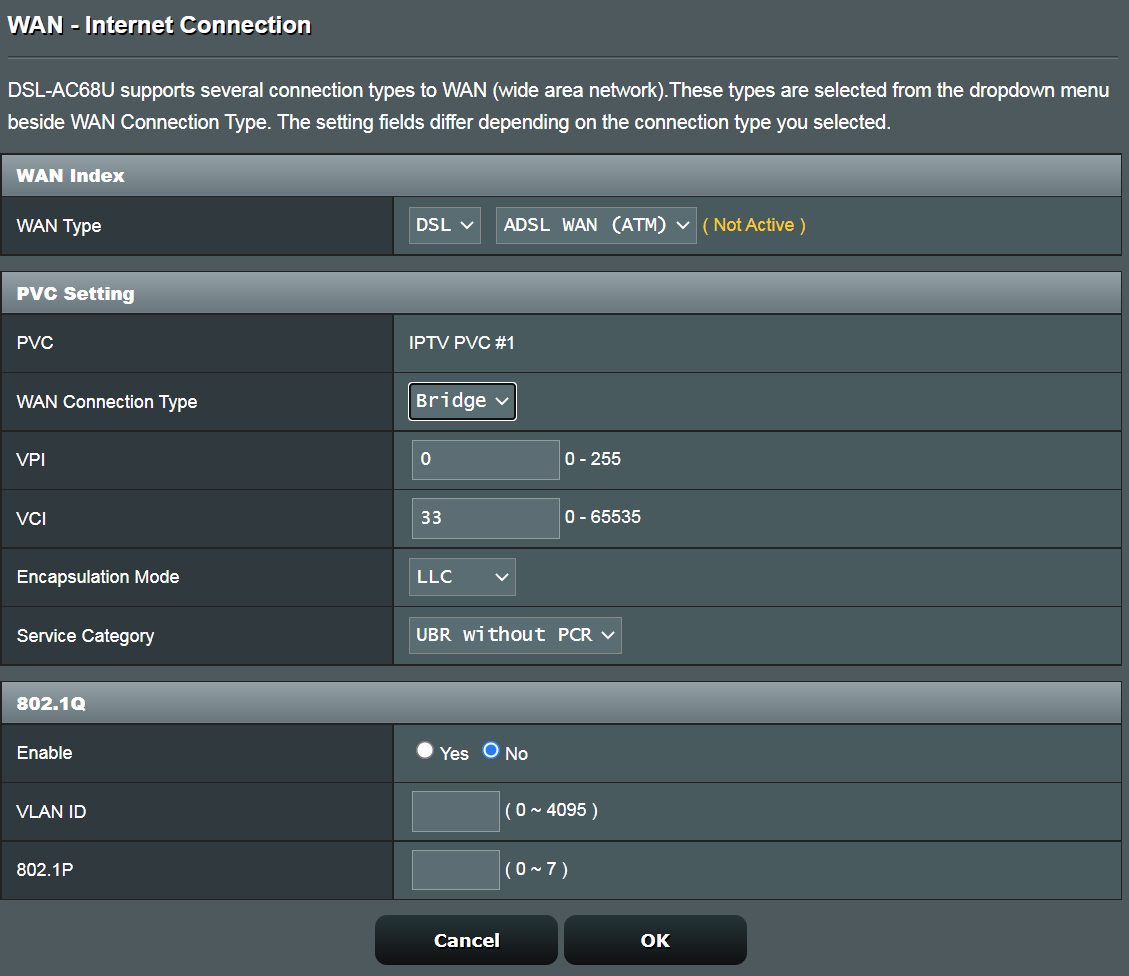
(5). Bridge
VPI / VCI: 0 / 33
If the above steps does not help and ISP has confirmed that the line is normal, please submit a feedback from web GUI for further troubleshooting.
Feedback steps
1) Reset to default settings, and complete the QIS.
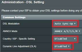
2) Set the [DSL Modulation to Auto sync-up].
3) Set the [Country / ISP - Specific Setting] to [Disabled].
4) Set the [Dynamic Line Adjustment (DLA)] to [Disabled].
5) Plug in a USB disk to the router.
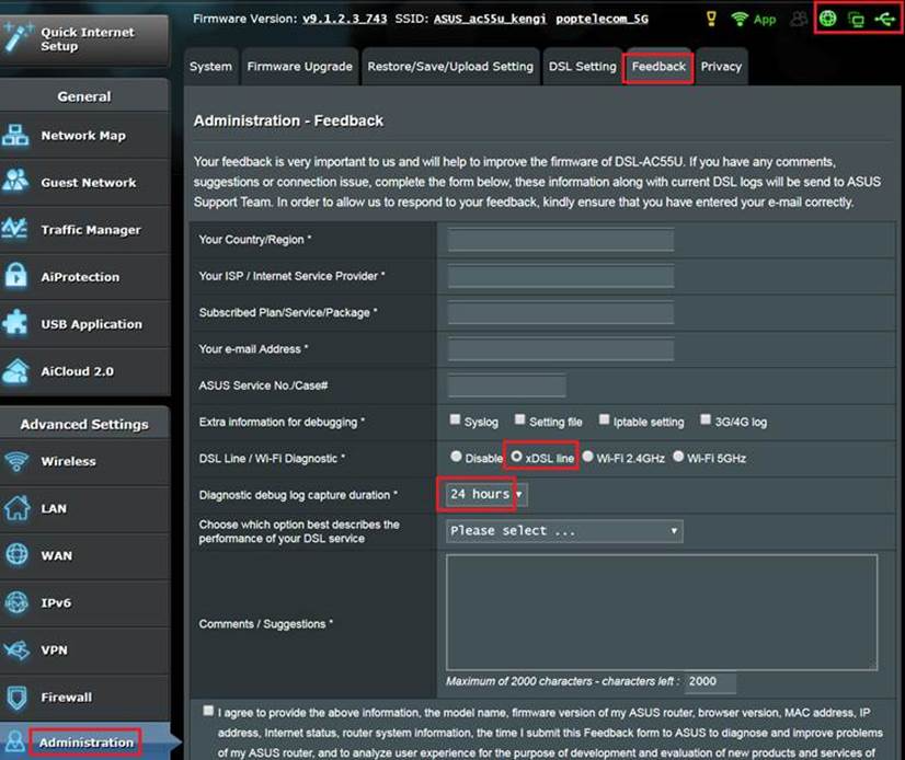
6) Submit a Feedback form with [DSL Line / Wi-Fi Diagnostic *] option set as [xDSL line] and [Diagnostic debug log capture duration] set as the time you think the problem will occur. (e.g. [24 hours], if there is no problem during this time, you will need to do this test again.)
7) Please notify us after the feedback is sent and provide the email used for sending and the test time you set (the system will automatically send the test log to us, we collect data by email)
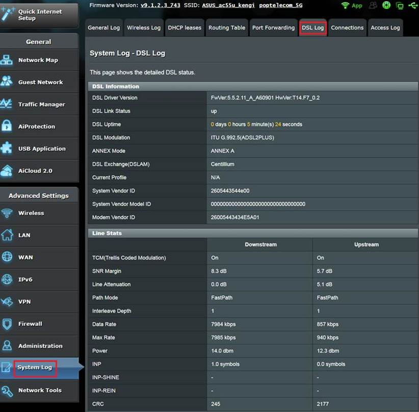
8) Provide us the [DSL Log] screenshots when normal and abnormal. (in System Log -> DSL Log page, not [System Log - General Log] page).
E.g.
9). When the Diagnostic debug log capture is done (The upper right corner connection icon changes back to green ), refresh the UI page, and click the exclamation mark in the upper right corner.
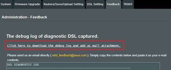
Then click the [Send debug log now]. (Need to insert the original USB disk.)
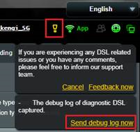
By doing so you will enter a special feedback page. Please click on the link below to save the debug log (WiFi.log.gz). Send it to us for analysis.
10). If the above steps cannot be performed or feedback fails to send for some reason, you can also send the log located in your USB to us via Support. (Logs will be located In USB:\asus_diagnostic\WiFi.log.gz)
11). After you send out the log and email, please contact ASUS service center to provide related information for tracking. https://www.asus.com/support/