[Motherboard] Introduction of ROG TRUE VOLTICIAN
ROG True Voltician communicates with the USB through the MCU, and opens the ROG True Voltician software to display it on the web, displaying the real-time voltage waveform curve of "OSCILLOSCOPE SYSTEM", and can record the relevant data in the "DATA ANALYSIS" and save it in *.CSV format.
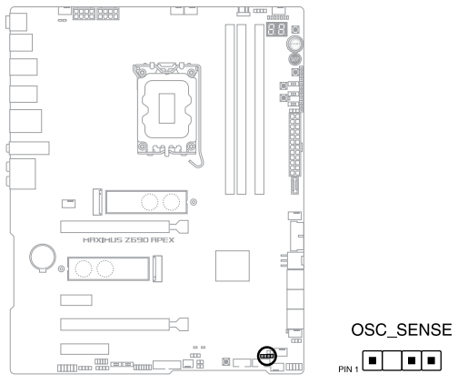
Applicable product models: ROG MAXIMUS Z690 EXTREME, ROG MAXIMUS Z690 APEX (equipped with ROG TRUE VOLTICIAN accessories)
Content :
Cable
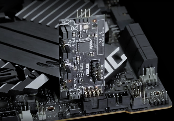
A. ROG TRUE VOLTICIAN overall overview:
B. How to install ROG True Voltician small card, there are two ways
ROG True Voltician connects the motherboard or Micro-USB Cable to the NB/PC DuPont cable connection method:
C. Sample installation method:
D. ROG TRUE VOLTICIAN [Software] Instructions:
E. Q&A
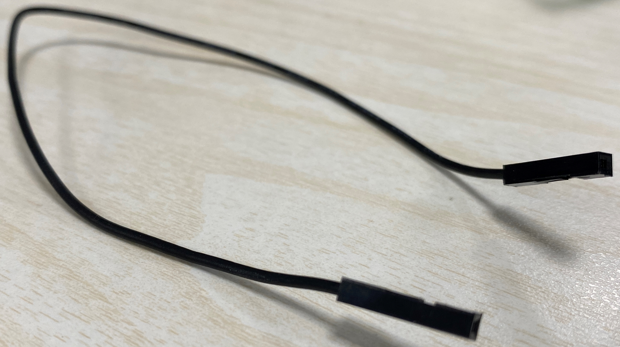
Cable:
Dupont line *4 (included)
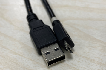
Micro-USB Cable (Prepare yourself)
A. ROG TRUE VOLTICIAN overall overview:
ROG TRUE VOLTICIAN [Small Card] Voltage measurement instructions: divided into 3.3V / 5V / 12V
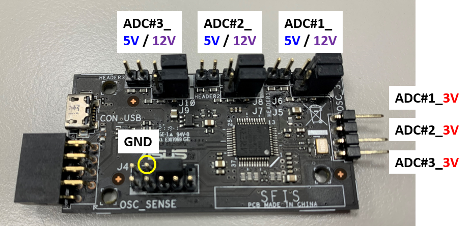
ADC =>analog to digital convert (analog to digital convert)
B. How to install ROG True Voltician small card, there are two ways:
The first way: the ROG True Voltician small card is inserted into the USB 2.0 Port of the MB upright.
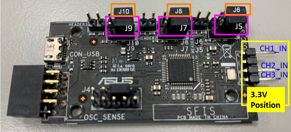
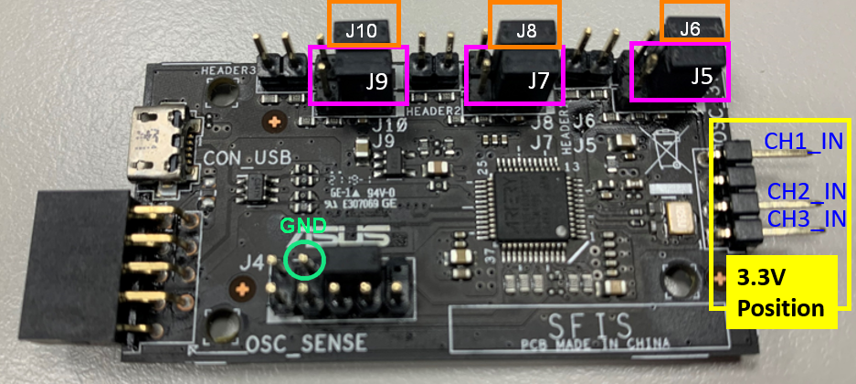
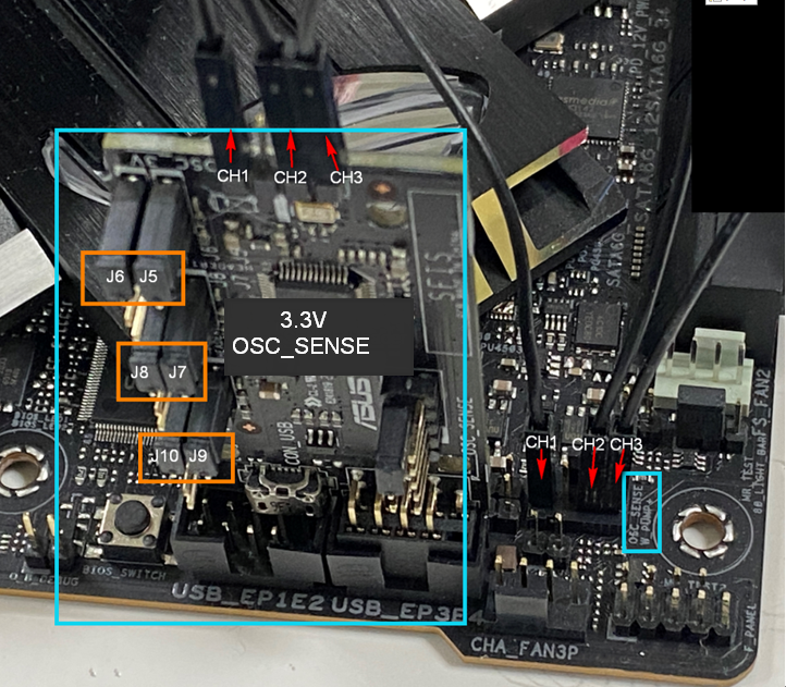
1. Measure the 3.3V ADC channel, there are three groups from top to bottom, namely CH1_IN, CH2_IN, CH3_IN, connected to the Dupont line
Please make sure that the Jumper (J5, J7, J9) (pink frame) is inserted on the [far right].
Please make sure the Jumper (J6 J8, J10) (orange frame) is inserted on the [far right].
*Please be careful not to input a voltage above 3.3V in the 3.3V measurement area to avoid damaging the MCU!!!
2.Measure 5V, ADC channels, from right to left, there are three groups, namely CH1_IN, CH2_IN, CH3_IN, connected to the Dupont line
Please make sure the Jumper (J5, J7, J9) (pink box) is inserted on the [left].
Please make sure the Jumper (J6 J8, J10) (orange frame) is inserted on the [left].
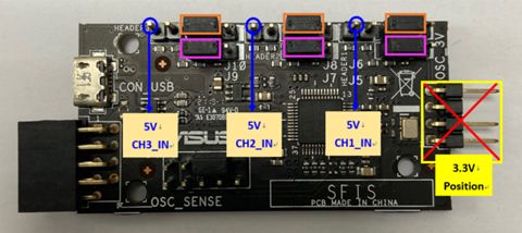
*Please be careful not to input a voltage above 5V in the 5V measurement area to avoid damaging the MCU!!!
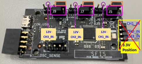
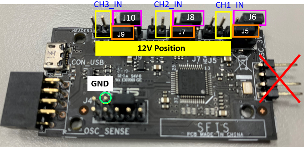
3.Measure 12V, ADC channels, from right to left, there are three groups, namely CH1_IN, CH2_IN, CH3_IN, connected to the Dupont line
Please make sure the Jumper (J5, J7, J9) (pink box) is inserted on the [left].
Please make sure the Jumper (J6 J8, J10) (orange frame) is inserted on the [right].
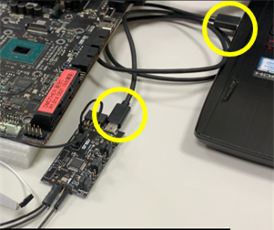
The second way: It can be connected to the motherboard local or external PC/NB through ROG True Voltician Micro-USB Cable.
1. Measure the 3.3V ADC channel, there are three groups from top to bottom, namely CH1_IN, CH2_IN, CH3_IN. Connect the Dupont line
Please make sure that Jumpers (J5, J7, J9) (pink boxes) are inserted on the [right].
Please make sure that Jumpers (J6, J8, J10 (orange boxes) are inserted on the [right].
*GND Pin usage scenario: (1) Cross-platform (e.g. PC/NB <-> MB) (2) Calibration of the measured voltage level to 0
*Please be careful not to input a voltage above 3.3V in the 3.3V measurement area to avoid damaging the MCU!!!
2. Measure 5V ADC channels, there are three groups, from left to right are CH1_IN, CH2_IN, CH3_IN.
Please adjust the Jumper (J6, J8, J10) first, and make sure that the Jumper is inserted on the [left] (such as the pink frame).
Please adjust the Jumper (J5, J7, J 9) first, and make sure that the Jumpers are all inserted on the [left] (such as the orange box).
*GND Pin usage scenario: (1) Cross-platform (e.g. NB <-> MB) (2) Calibration of the measured voltage level to 0
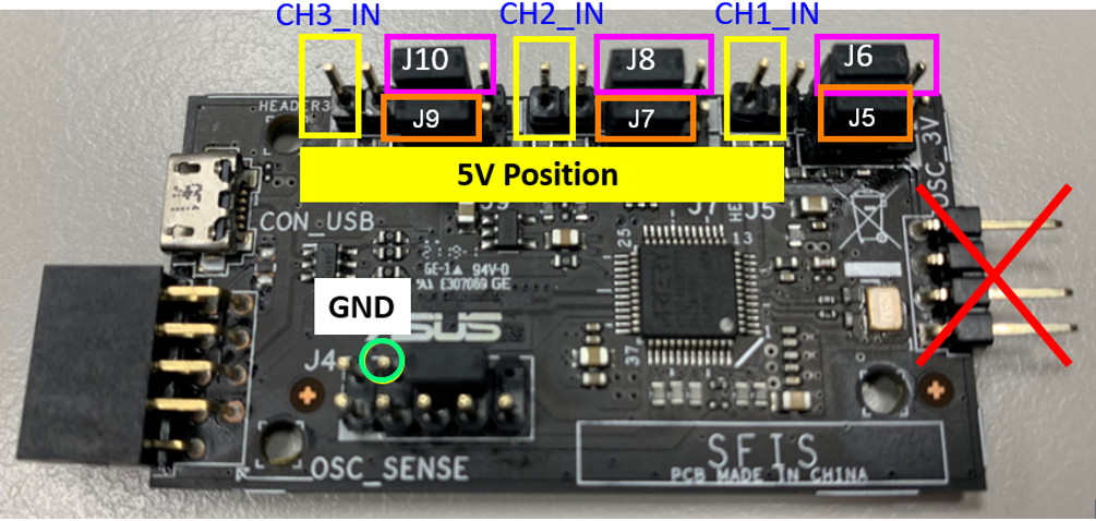
*Please be careful not to input a voltage above 5V in the 5V measurement area to avoid damaging the MCU!!!
3. Measure 12V ADC channels, there are three groups, from left to right are CH1_IN, CH2_IN, CH3_IN.
Please adjust the Jumper (J6, J8, J10) first, and make sure that the Jumper is inserted on the [right side] (such as the pink box).
Please adjust the Jumper (J5, J7, J 9) first, and make sure that the Jumpers are all inserted on the [left] (such as the orange box).
*GND Pin usage scenario: (1) Cross-platform (e.g. NB <-> MB) (2) Calibration of the measured voltage level to 0
Example Sample installation method:
(ROG MAXIMUS Z690 APEX), just install it on the USB PIN, measure 3.3V OSC_SENSE Header
Suggested Dupont line connection method and location:
1. Measure 3.3V
Step 1. Connect the Dupont cable to the GND pin of the small card and the GND pin on the motherboard
Step 2. Dupont cable connects the 3.3V area of the small card with the OSC_SENSE Header of the motherboard
2. Measure 5V
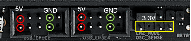
Step 1. Connect the Dupont cable to the GND pin of the small card and the GND pin on the motherboard
Step 2. Connect the Dupont cable to the 5V area of the small card and the red circle 5V pin of the USB 2.0 port on the motherboard
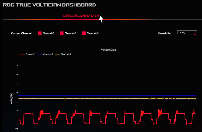
ROG TRUE VOLTICIAN [Software] Instructions: OSCILLOSCOPE SYSTEM
1. For download and installation, please refer to Q&A Q1,
2. Click the ROG True Vlotician icon, the webpage will automatically open
ROG TRUE VOLTICIAN [Software] Instructions: OSCILLOSCOPE SYSTEM & DATA ANALYSIS
1. OSCILLOSCOPE SYSTEM: to display the waveform curve in real time
2. DATA ANALYSIS: Record related data
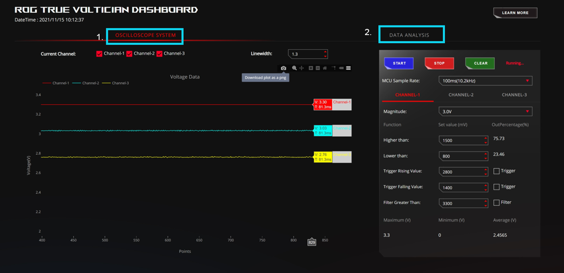
Note [refresh button] [F5] or [Ctrl+R] refresh the page, [all settings will be restored to default].
*The default browser for Windows 10 / Windows 11 is Microsoft Edge. (Compatible with Google Chrome)
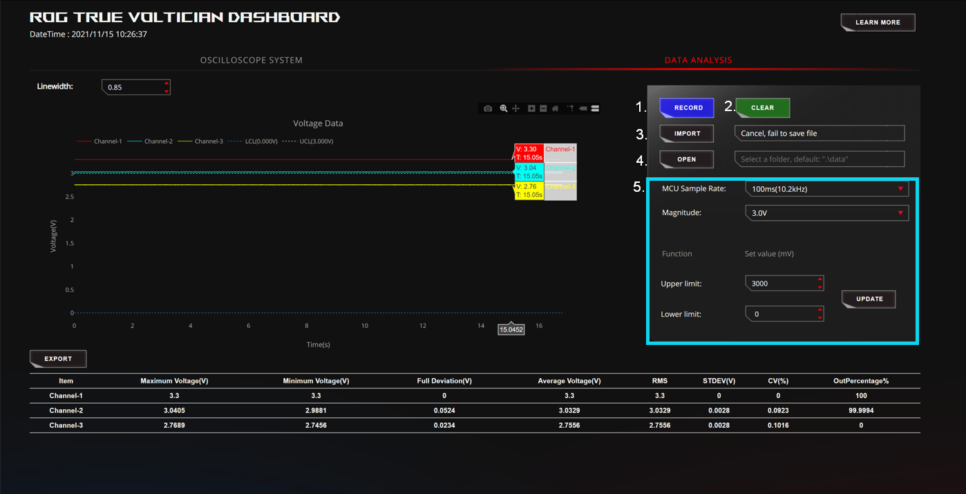
2. DATA ANALYSIS: Record related data
1. RECORD: Record start and pause RECORD & STOP
2. CLEAR: Clear all set values
3. IMPORT: load (past log file).csv
4. OPEN: The folder where records are stored
5. Set up the MCU:
Q&A
Q1. Download and install ROG TRUE VOLTICIAN [Software]
A1:
1. Please go to the ASUS download point to download the ROG True Voltician software
https://rog.asus.com/motherboards/rog-maximus/rog-maximus-z690-apex-model/helpdesk_download
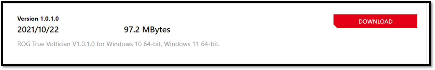
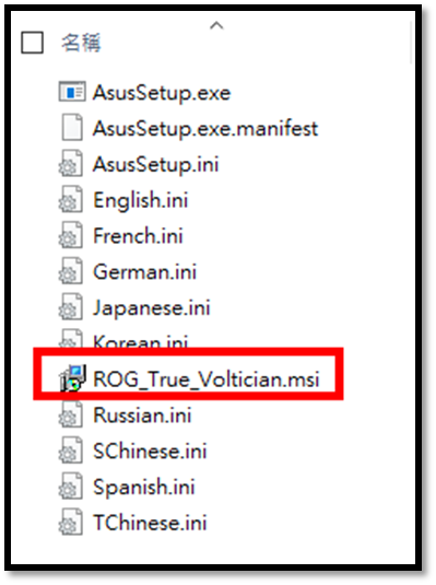
2. File name

3. After unzipping, select ROG_True_Voltician.msi
4. Start the installation, select Next
5. End User License Agreement, select Next
6. Installation status
7. finish installation, select Finish
8. ROG True Voltician icon appears on the desktop
Q2. The voltage value of the management interface "OSCILLOSCOPE SYSTEM" of ROG True Voltician will not change?
A2: You can close the browser used by this "OSCILLOSCOPE SYSTEM" first, and then re-open the ROG True Voltician software
Or confirm Q3: Is there any damage to ROG TrueVoltician?
Q3: How to confirm that ROG TrueVoltician is damaged?
A3:
1. Enter the ROG TrueVoltician software and display "Error: mcu cannot be found..."
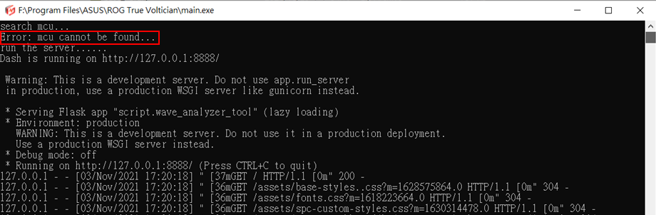
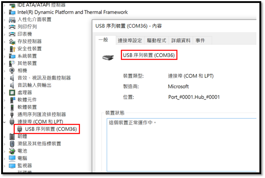
2. And enter the device manager, there is no display of "Ports (COM and LPT)"-USB serial device, for example: USB serial device "COM36" (no display),
You can turn it off first, and reconfirm the ROG True Voltician card, whether it is connected to the motherboard or USB Cable (please refer to: B. How to install the ROG True Voltician small card)
*Please be careful not to input a voltage exceeding 3.3V/5V in the 3.3V/5V measurement area to avoid damaging the MCU!!!
If the problem persists, please contact your local ASUS service center.