[NUC] En-tête de panneau avant pour NUC
Keep HTML tag:Most, but not all, NUC motherboards have a 9-pin or 11-pin (2.0 mm pitch) front panel header. This header is on the processor/fan side of the motherboard. You can connect a power switch to this header to remotely power on or reset an Intel NUC board that is embedded (such as in a kiosk) in a position in which the chassis' power switch isn't easily accessible.
Click or the topic for details:
9-pin header information
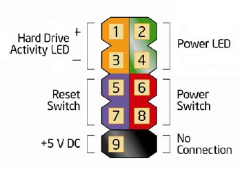
Pin assignments:
| Pin | Description | In/Out | Pin | Description | In/Out |
| Hard Drive Activity LED | Power LED | ||||
| 1 | Hard disk LED pull-up to +5V | Out | 2 | Front panel green LED (5V) | Out |
| 3 | Hard disk activity LED | Out | 4 | Front panel yellow LED (5V) | Out |
| Reset Switch | On/Off Switch | ||||
| 5 | Ground | 6 | Power switch | In | |
| 7 | Reset switch | In | |||
La plupart, mais pas toutes, des cartes mères NUC ont un connecteur de panneau avant à 9 ou 11 broches (pas de 2,0 mm). Ce connecteur se trouve du côté du processeur/ventilateur de la carte mère. Vous pouvez connecter un interrupteur d'alimentation à ce connecteur pour allumer ou réinitialiser à distance une carte Intel NUC incorporée (comme dans un kiosque) dans une position où l'interrupteur d'alimentation du châssis n'est pas facilement accessible.
Cliquez sur le sujet pour plus de détails:
Informations sur le connecteur à 9 broches
Affectations des broches :
| Broche | Description | Entrée/Sortie | Broche | Description | Entrée/Sortie | |
| LED d'activité du disque dur | LED d'alimentation | |||||
| 1 | Résistance de tirage de la LED du disque dur à +5V | Sortie | 8 | Terrain | ||
| Puissance | Non connecté | |||||
| 9 | Puissance | Sortie | 10 | Aucune broche | ||
Informations sur l'en-tête à 11 broches
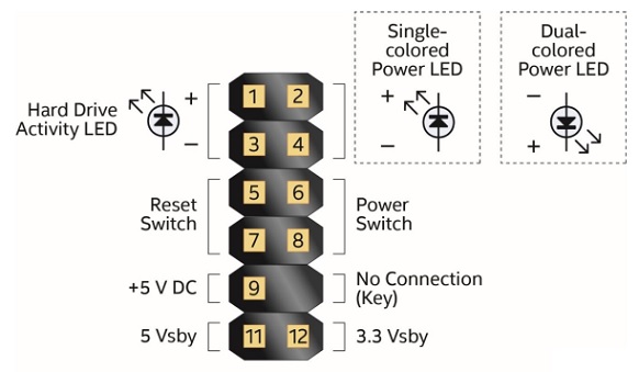
Affectations de broches :
| Broche | Description | Entrée/Sortie | Broche | Description | Entrée/Sortie | ||||||||||||||||||||||||||||||||||||||||||||||||||||||
| DEL d'activité du disque dur | DEL d'alimentation | ||||||||||||||||||||||||||||||||||||||||||||||||||||||||||
| 1 | Résistance de tirage de la DEL du disque dur vers +5V | Sortie | 2 | DEL du panneau avant (couleur principale) | Sortie | ||||||||||||||||||||||||||||||||||||||||||||||||||||||
| 3 | DEL d'activité du disque dur | Sortie | 4 | DEL du panneau avant (couleur alternative) | Sortie | ||||||||||||||||||||||||||||||||||||||||||||||||||||||
| Bouton de réinitialisation | Bouton marche/arrêt | ||||||||||||||||||||||||||||||||||||||||||||||||||||||||||
| 5 | Terrain | 6 | Bouton d'alimentation | Entrée | |||||||||||||||||||||||||||||||||||||||||||||||||||||||
| 7 | Bouton de réinitialisation | Entrée | 8 | Terrain | |||||||||||||||||||||||||||||||||||||||||||||||||||||||
| Alimentation principale | Non connecté | ||||
| 1 | +19 V DC - VCC | 2 | No pin | ||
| 3 | GND | 4 | No pin | ||
| 5 | +12 V DC - VCC12 (1,5 A courant nominal) | 6 | No pin | ||
| 7 | GND | 8 | No pin | ||
| Alimentation principale (alternative) | Non connecté | ||||
| 9 | +5 V DC - VCC5 (1 A courant nominal) | 10 | No pin | ||
| Alimentation de veille | |||||
| 11 | 5 V en veille - 2 A courant nominal | 12 | 3,3 V en veille (1 A courant nominal) | ||
- Above information might be partly or entirely quoted from exterior websites or sources. please refer to the information based on the source that we noted. Please directly contact or inquire the sources if there is any further question and note that ASUS is neither relevant nor responsible for its content/service
- This information may not suitable for all the products from the same category/series. Some of the screen shots and operations could be different from the software versions.
- ASUS provides the above information for reference only. If you have any questions about the content, please contact the above product vendor directly. Please note that ASUS is not responsible for the content or service provided by the above product vendor.